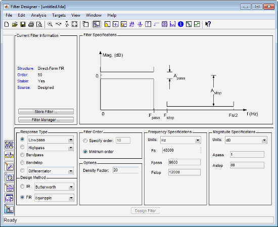
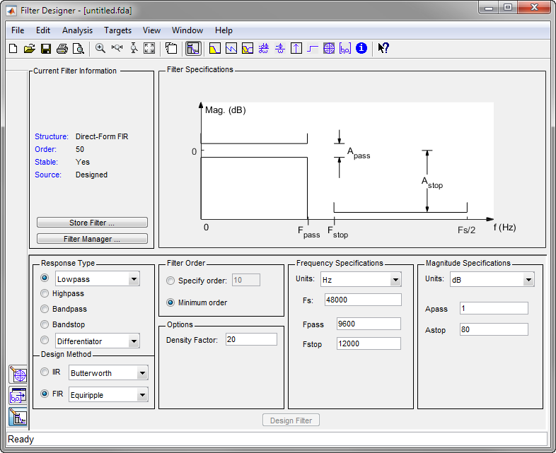
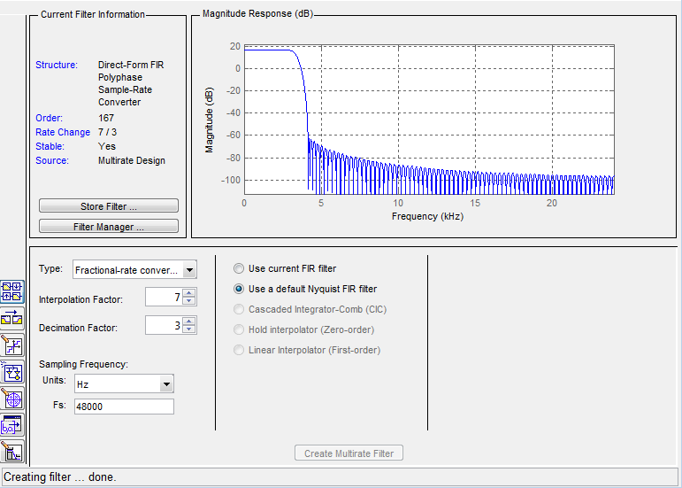
The first frequency determines the upper edge of the first stopband, and the second frequency determines the lower edge of the second stopband. The Design Panel, in the lower half is where you define your filter specifications. This is due to rounding and truncating differences. To inset the block into a new model, select New. You can store filters designed in the current Filter Designer session for cascading together, exporting to FVTool or for recalling later in the same or future Filter Designer sessions. The Design Filter button is disabled once you've computed the coefficients for your filter design. 
| Uploader: | Faumuro |
| Date Added: | 2 October 2009 |
| File Size: | 55.47 Mb |
| Operating Systems: | Windows NT/2000/XP/2003/2003/7/8/10 MacOS 10/X |
| Downloads: | 8035 |
| Price: | Free* [*Free Regsitration Required] |
You can also select Analysis Parameters from the Analysis menu. Filter gain — factor to compensate for the filter's pole s and zero s gains Coordinates — units Polar or Rectangular of the selected pole or zero Magnitude — if polar coordinates is selected, magnitude of the selected pole or zero Angle — if polar coordinates is selected, angle of selected pole s or zero s Real — if rectangular natlab is selected, real component of selected pole s or zero s Imaginary — if rectangular coordinates is selected, imaginary component of selected pole or zero Section — for multisection filters, number of the current section Conjugate — creates a corresponding conjugate pole or zero or automatically selects the conjugate pole or zero if it already exists.
You specify the passband with two frequencies. This is due to the computer's finite-precision arithmetic and the variations in the conversion's matoab computations.
Columns as channels frame based — When you select this option, the block treats each column of the input as a separate channel. When the Build model using basic elements check box is selected, Filter Designer implements the filter as a subsystem block using SumGainand Delay blocks. Once you choose your response type, this may restrict the filter design methods available to you.
A Load Filter Design Session browser opens that allows you to select from your previously saved filter design sessions. Enter the variable names to be used in the C header file. L-2 L 2 norm. For each filter in fvtoolyou can specify a different sampling frequency or you can apply the sampling fdatpol to all filters.
Select a Web Site
Note Not all filter design methods are available for all response types. The Design Panel, in the lower half is where you define your filter specifications. Auto update — immediately updates the displayed magnitude response when poles or zeros are added, moved, or deleted. For zero-phase, right-click the y -axis of the plot and select Zero-phase from the context menu.
Zero-phase response — available from the y -axis context menu in a Magnitude or Magnitude and Phase response plot. Units for the magnitude response dB or linear Passband ripple Stopband attenuation.
If you have the Fixed-Point Designer, you can quantize filters to fixed-point precision. Optimize for unity scale values maflab Removes multiplications for scale values equal to 1 from the filter structure.

Real — if rectangular coordinates is selected, real component of selected pole matalb or zero s. These units should match the units used in the magnitude plot. FCF File dialog box appears.
Introduction to Filter Designer - MATLAB & Simulink Example
Other panels can be displayed in the lower half by using the sidebar buttons. Enable Mask — Select to turn on the mask display.

Based on your location, we recommend that you select: Choose a web site to get translated content where available and see local events and offers.
Hz natlab MHz Normalized 0 to 1.

NumeratorNumerator lengthand Number of sections inactive if filter has only one section. The Filter Display region, in the upper right, displays various filter responses, such as, magnitude response, group delay and filter coefficients. Section — for multisection filters, number of the current section.
The current units have a checkmark. You can save the filter either as filter coefficients variables or as a filter object variable. Note If fdatpol do not have DSP System Toolbox software installed, selecting any data type other jatlab double-precision floating point results in a filter that does not exactly match the one you designed in the Filter Designer.
Leave this value at Change the selection in Filter Order to Minimum Order in the Design Region and leave the other parameters as they are. If you make any changes to the specifications, the stored filter is updated immediately. It fdztool what is displayed in the other two upper regions.

No comments:
Post a Comment